Passage of Speed Ring & Draw frame
Introduction:
Speed frame is that the machine wherever the sliver is subjected to 1 or additional attenuating method to the attenuated sliver receive atiny low quantity of twist and is wound on spool appropriate for creeling at next method. Roving is that the output product of speed frame. it’s fine fiber stands that is employe within the notice method of preparation for spinning. it’s loosely twist stands of fibers.
Objects:
- To draft the drawframe sliver to reduce weight per unit length.
- To insert small amount of twist into the roving.
- To wind twisted roving onto the bobbin.
- Attenuation of drawn sliver to from roving or required count of drafting.
- Insert small amount of twist give required strength to roving.
- Build the roving in full length of bobbin in such a from which will facilitate handling, transfers and feeding to ring frame.
Tasks or Functions of Speed Frame
The tasks of a speed frame machine is also divide into variety of individual operations, every of that is sort of freelance of the others.
The major tasks of the speed frame method are list as follows:
Drafting: to scale back the scale of the strand.The draw frame sliver feed to the speed frame is reduce in size by the action of drawing and drafting. So that, the reduced size of the roving is among the drafting vary of the ring frame.
Twisting: to impart necessary strength.Spiraling the fibres around one another concerning the axis of the strand thus to bind themselves along to impart adequate strain, to alter it to build-up within the type of an appropriate package, convenient to handle from one method to a different. Here, the quantity of twist used ought to be simply adequate to carry the fibres along however it ought to preclude drafting within the ring frame.
Laying: to place the coils on the bobbins.To put the coils on the spool in regular arrangement in order that, no over imbrication or excess spacing between the coils will occur. The coils ar ordered facet by facet throughout the build of the spool. This operation is finishe by alternate reversing motion of the spool rail.
Winding: to wind sequent layers on the spool at the right rate of speed.To put sequent layers of roving on the spool at a correct rate of speed. The speed being rule by the building motion with the assistance of differential motion.
Building: to shorten sequent layers to form round shape ends on the package of roving.
elements
- Separators/Spacer
- Guide rollers
- Drafting rollers
- Dead weight
- Flyers
- Spindles
- Motor
- Bottom rollers
- Rubber-covered prime on-line rollers
- Top arm
- Aprons (top and bottom)
- Condenser (inlet and floating)
- Pressure arm
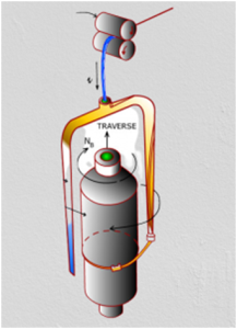
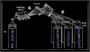
Material Passage Diagram of Speed Frame:
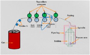
Fig: Material Passage Diagram of Speed Frame
Description:
The feed material return from speed frame i.e. roving bobbin is placed on the basket. The basket that is hookup to the machine is umbrella sort.
Then feed material is passe underneath the guide rollers and thru the trumpet in to the drafting zone. Here some draft is inserte in to the roving. The draft system is three over three drafting system with apron. The delivery material that’s deliverefrom the front roller is reache to the somebody over gas waste collector, lappet and thru balloon dominant ring. Lappet is employe to regulate the fabric path and balloon dominant ring is employ to regulate the balloon formation and spinning tension. Here roving is twist by the movement of the somebody round the ring. The yarn is then wound on the ring cop.
Calculation of twist, twist constant of the roving frame or speed frame
Twist is that the spiral turns give to a yarn to extend the strength of the yarn. however in speed frame machine vary bit of twist is give to the roving to form it ready to wound onto a spool. For a fibrous material twist is measure by the parameter twist per in. (TPI), twist per cm or twist per meter (TPM). For the cotton sample twist is measure by TPI.
In speed frame machines twist per unit is varied with the variation of stuff and its completely different parameters. This variation of twist is insert by dynamical a wheel that’s connect with the most driving shaft name twist amendment pinion (TCP). and also the multiply of TCP and TPI, gift during a machine is name twist constant. This price is applicable for any need twist with corresponding TCP. thus we will resolve the desire TCP to induce a given TPI.
The generalize formula is as below:
Specification:
Front roller carrier wheel: 80T(A)
Twist constant amendment pinion carrier: 30T(B)
Twist constant amendment pinion: 30T(C)
Twist amendment pinion: 28T(D)
Sprocket wheel: 34T(E)
Sprocket pinion: 36T(F)
Spindle carrier wheel: 40T(G)
Spindle wheel: 22T(H)
Speed frame is that the initial machine that allows the winding of the fibrous material on to a package.
This machine gives the fiber a circular form, which greatly benefits its use in ring spinning. As a result, the machine holds significant importance. In this experiment, we illustrated different gearing diagrams of the twist-inserting section, identified their functions, and calculated the twist and twist constant of the roving frame. The results met our expectations, making the experiment a successful one.
Ring Spinning Machine: Different Parts and Functions,Drafting System
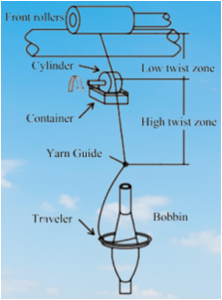
The ring frame process is the last and the most important process in the yarn manufacturing process.
The ring frame is the machine that converts roving into yarn of the desired count. It is the most commonly use method in the yarn manufacturing process.
In the ring frame process, the roving from the simplex machine serves as the input material. The machine simultaneously performs three operations—drafting, twisting, and package formation—in a continuous manner. The material undergoes drafting multiple times based on the required yarn count. After drafting, the machine inserts the necessary amount of twist into the fiber strand to bind the fibers tightly. The resulting yarn is then wound onto a ring bobbin.
Since ring bobbins hold only a small amount of yarn, the yarn is subsequently transferr onto larger packages such as cones, cheeses, or spools.
This machine is suitable to spun cotton, synthetic and many other fibres efficiently.
The widest range of yarn count can be spun on the ring frame. The yarn produced on the ring frame machine has very good tensile strength, elongation percentage, yarn evenness and hairiness properties. The ring spun yarn is more expensive than open end yarn.
This ring spinning was much more productive, simpler in mechanism, easier in manipulation and more economic. This was the origin of ring twisting, probably the most extensively used system for the processes of simultaneously twisting yarn and winding it onto a package
It is the machine by which yarn is manufacture at required specification for specific purposes. At that time improved type of spindle with good lubricating system and different ball- or roller- bearing and improved damping used in different places of drafting zones and spindle respectively. In 1888 it become a perfect form and can be give production effectively.
Objects :
Following are the core objects of ring spinning-
- To wind up the resulting yarn on to bobbin.
- To build up the yarn on to bobbin in form of a suitable for storage, transportation and processing.
- To draft the roving fed to the ring frame.
- To impact the strength to the fibre strand by twisting.
- Creeling: By this process the drawn sliver is introduce to the draft zone from sliver can manually.
- Drafting: To reduce the weight per unit length by drafting i.e, passes of sliver through three or four pair of roller of different speed.
- Twisting: To make turn within the fiber of the drafted material to hold them together.
- Winding: To wound the roving or to upright bobbin in a particular manner so that it can be use in the next machine easily.
- Building: By this process the roving is wind in full length of the bobbin in such a form which will facilitate handling, transfer and feeding to ring frame.
- Doffing: Doffing is to replace an empty bobbin at the place of fully wound bobbin.
Drafting system:
Drafting system makes important role at yarn quality and performance of the machine. Normally 3 over 3 drafting system is use at ring frame. draft distribution and arrangement of drafting system is very important both for yarn quality and machine performance. Total draft, break draft and distribution of draft for different yarn are given below:
Total draft = Break draft or break zone draft X Front zone draft
- Bottom rollers are flutesteel roller.
- Top rollers are rubber roller, which are pivote at weighting arm can apply pressure 15-25 daN to the bottom roller.
- Apron is a endless synthetic rubber small belt, which guide the drafted fiber.
- Hardness level of top back roller 80°- 85° shore and 63°- 65° shore at top front roller.
- Different parts:
- Roving bobbin
- Roving
- Bobbin holder
- Guide roller
- Drafting arrangement
- Guide
- Lappet
- Bobbin tube
- Ring
- Ring rail.

Important parts :
Spindle:
Spindle is a hollow cylindrical tube, consists of mainly two parts (upper parts bolster) and capable to run high speed. Normally upper part of spindle is taper, which holds ring cop and bolster is fixed to the ring rail by nut. Spindle is drive by tape at the position of whorl. The diameter of whorl is important for high speed.
Lappet:
Lappet consists of thread guide and an arm. This thread guide lead the yarn centrally over the spindle axis and arm fix at lappet rail.
Ballon control ring:
Ballon control ring is a ring, which control or reduces the diameter of yarn ballon at middle position. Actually it divided the ballon into two sub-ballons. Normally yarn ballon is forme during twisting and winding of yarn at ring spinning machine.
Separator:
Separator is an aluminum or plastic plate, which is place between the individual spindle to prevent the hurl of broken thread to neighboring yarn making ballon.
Ring:
This is the renowned ring, so for the frame is name as ring spinning frame. Most commonly carbon steel is used; but different hardene steel is also use. The ring is tough and hard. The range of its surface hardness is between 800-850 vickers. Ring diameter varies 38-54 mm.
Traveller:
This is the tiny key parts of ring spinning frame which travels around the ring at 30-35 m/sec and impart twist to the yarn. The hardness of the running traveler must be within 650-700 vickers. Contact pressure between ring and traveler is up to 35N/mm². Generate high temperature (300-400°C). the mass of traveller is 16-120gm/1000.
Ring cop:
Yarn is windaround ring cop by cop building mechanism. There are approximately 100-200 gm yarn present in every ring cop.
Factors affects the quality of the yarn
Ring spinning is the first stage of post spinning in which yarn produced from the roving installed on the hanger on the ring machine. Ring process is the heart of the textile plant and there is a lot of factors which has an effect on the yarn quality.
- The speed of machine makes a major role on the yarn quality, as the speed increase of the ring machine, the imperfection (Neps 200%, Thick +50, Thin -50) of yarn increase.
- Hairiness is also affect by ring production process and mainly produce by the movement of burnt traveller and high speed of the machine.
- CV of the count is also very important and the ring spinning process is the last stage of the process where we can reduce the CV of yarn count.
- The imperfection of yarn count from a quality point of view is so important that every customer required this quality standard, that imperfection should be as minimum as possible.
- Ring spinning process also effects on twist variation during manufacturing of yarn. It causes major problems during working in the next process.
Main advantageous :
- Most usable spinning machine in the world.
- Fine to coarse (5-1000 tex) yarn can be produce.
- Yarn has very good strength.
- Yarn is suitable for all next process.
- More than 80% of total yarn is produce by ring spinning machine.
Limitations :
- Low twisting rate
- Low production
- Small bobbin size
- Frequent doffing
- High energy consumption
- Limited speed of traveller
Draw Frame
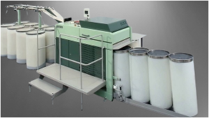
is a machine for combining and drawing slivers of a textile fiber (as of hemp for rope manufacture or cotton for spinning). Draw Frame is that the operation by that slivers area unit merging, double and leveled. in brief staple spinning the term is barely apply to the method at a draw frame.In the drafting arrangement every combine of rollers move quicker.
Objects of Draw Frame:
To develop the yarn quality, particularly yarn evenness through increasing sliver quality
- On the slivers the fibers ought to be straight.
- To make them be a way parallel to the sliver axis and neighbors.
- To improve the evenness of the sliver.
- To improve the uniformity of the sliver.
- To remove the dirt from the sliver.
- To make excellent mixing of the part.
- Doubling: The method of hairdressing 2 or a lot of sliver rovings or yarns into one is termed doubling. This term isn’t restrict to the mix of 2 units solely.
- Draft: The reduction of weight / yard of sliver and therefore the increase long is termed drafting. Or Attenuation of sliver while not breaking is termed draft
- Drafting: The method of attenuating or increasing length per unit weight of sliver. it’s principally because of the peripheral speed of the roller.
Functions of Draw Frame
- Equalizing: One of the focal responsibilities of the draw frame is refinement evenness over the short, medium and future. Card slivers serve to the draw frame possess a degree of unevenness that can’t be acknowledge for manufacturing yarn.
- Parallelization: Attaining associate optimum price for persistency within the yarn, the fibers ought to be aligneparallel within the fiber strands by drafting method.
- Blending: Into the discount of equalizing influence, doubling additionally offers a prime notch of compensation of staple inequality by mixing. Here various varieties of fiber may be combine altogether to accumulate a selected mix quantitative relation. E.g. 65:35 PC, 55:45 CVC etc.
- Dust removal: The draw frame is associate upright dirt eliminating instrument. High performance draw frames area unit fitted out with correct suction systems. The draw frame extracts quite eighty you look after the incoming dirt.
- Passage of fiber

- Fig: Passage of Draw frame
- The primary components of draw frame’s drafting arrangement area unit expressed below-1.Bottom roller: Bottom rollers area unit fabricated from steel driven from main gear transmission. very cheap rollers area unit following type:2. Prime roller: Top rollers don’t seem to be completely driven. they’re driven with the surface contact of very cheap roller. prime rollers area unit coated with rubber. The hardness of rubber ought to be adjuste fastidiously. Hardness is per terms of degree shore.
- Soft
60-70 o shore Medium 70-90 o shore Hard above o shore 3. Prime roller pressure: To clamp the fibers, the highest rollers should be forced at a high towards very cheap rollers. The pressure may be generate by following suggests that.
- Dead weight (Now obsolete)
- Spring loaded (The most usual form)
- Hydraulic system (Rarely used)
- Pneumatic system (Rieter)
- Magnetic (Saco Lowell)
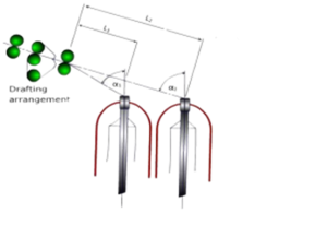
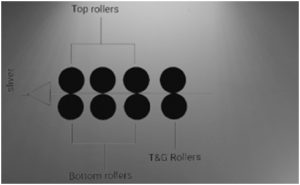
- Types of Drafting Arrangement

- Fig: Drafting Arrangement
- Conventional 4/4 roller drafting system.
- 3/4 roller drafting system.
- 3/3 roller drafting system with pressure bars.
- 4/3 roller drafting system with pressure bars.
- 5/4 roller drafting system
- Principle of roller setting:
- Longer staple length wider setting and contrariwise.
- Greater the majority of the fabric wider the setting.
- Faster the drafting roller speed wider the setting.
- Higher the degree of compactness wider the setting.
- For harsh and rough style of fiber setting are wider as they don’t pass simply.
- Defects of Draw Frame:There area unit several defects of draw frame, from these some area unit delineated below,
- Fine sliver or finish missing: Any sliver might break once doubling is 5-6; this is often call fine sliver or finish missing. The causes of this fault area unit could also be Faulty stop motion device and operators carelessness.
- Irregular sliver: for 2 reason the sliver could also be irregular, these are,
- Roller slip: Improper roller pressure, Worn prime roller, Eccentric prime roller.
- Defective drafting system: Improper roller setting.
- Long fiber within the waste.
- Roller overlapping: The causes of roller lapping area unit,
- Improper improvement of the roller.
- Improper temperature.
- Improper ratio.
- Excessive sliver breaks: The causes of excessive sliver breaks area unit,
- Feed zone: Feed tension.
- Draft zone: Roller overlapping, web of sliver in will.
- Delivery zone:
- Improper stock filling.
- Thick and skinny place.
- Uneven web.
- Bad whorled.
Causes of Draw Frame potency loss:
- Roller overlapping.
- Sliver breakage.
- Doffing.
- Schedule maintenance.
- Quality check.
Differences between Carded Sliver and Drawn Sliver
| Carded Sliver | Drawn Sliver |
| The fibers are oriente in all direction. | The fibers are orient to the sliver axis. |
| Sliver contain leading hook, tailing hook and both end hook. | The hooks are straighten. |
| Many fibers are projecte out from the sliver | Less fibers are projecte] out from the sliver |
| Irregular weight/unit length | More regular weight/unit length due to doubling and auto leveling |
RELATED LINK