
DETAIL STUDY OF LATHE MACHINE

Lathe is one of the largest versatile machine tools in the industry, used for various machining processes. The lathe tool is mount and various functions are rotate.
Principle of work:

A lathe may be a machine that holds a piece piece between 2 rigid strong supports referred to as a middle or that rotates in an exceedingly chuck or face plate. Cutting tools area unit command tightly and only within the tool post that is give for rotating work. traditional cutting operations are perform by parallel or cutting tools.
The main perform of the work path is to insert the fabric and provides the work pile the required form and size. throughout the shaper journey, the work piece for dropping the fabric rotates the tool files and becomes the direction feed of the tools.
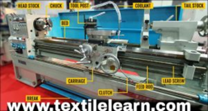
The main elements of the shaper are:
Headstock: The support is typically situate on the left stock of the shaper and is supply with gears, spindles, chuck, gear speed management levers and feed controllers.
Accessories mounted on the support spindle are:
Three jaw chucks
Four jaw chuck.
Leth Center and Leth Dr.
Collet Chuck.
Face platform.
Magnetic chuck.
Tailstock:
Commercially situated in shaper Uja, the work piece is that the last.
The basic perform of support is:
To support the opposite finish of the work whereas machining. Holding a tool for drilling, reaming, sound etc. operations.
Bed:
The main a part of the shaper, all the elements area unit latched to the bed. These embrace support, tailstock, carriage rail and different elements.
Carriage:
Carriage Located between support and support and has apron, saddle, compound rest, cross slide and gear post.
It has five main parts:
Saddle
Cross slide
Compound rest
Tool post
Apron
Saddle:
It is AN H-shaped casting mounted on high of a shaper wedge. It supports cross-slide, compound rest and gear post.
Cross slide:
The cross slide is given a feminine joggle on one aspect and its male joggle at the highest of the saddle.
T slots area unit provided on the side of the cross slide to modify fixing of the rear tool post or fluid attachment. The carriage essentially provides mounting or automatic cross-movement for the cutter.
Compound rest:
At the highest of the cross slide is that the compound rest. This tool supports post and cutting tools in its numerous positions
Tool post:
Tool Post
The tool post mounts on the compound rest and holds various cutter holders. These holders rest on a wedge at the bottom, which fits into a concave-shaped ring (segmental type). This design allows users to adjust the height of the cutting edge by tilting the tool post. The tool post attaches to the top slide and moves through the actions of the saddle, cross slide, and top slide.
Lead Screw
The lead screw moves the carriage mechanically during threading operations.
Feed Rod
The feed rod drives the carriage either from left to right or in the reverse direction.
Chip Pan
The chip pan, located at the base of the shaper, collects chips produced during the shaping operation.
Hand Wheel
The hand wheel allows the user to manually move the cross slide, carriage, support, or any other part connected to a hand wheel.
Lathe machine area unit typically divided into 3 types: Engine shaper, Turret shaper and Special Purpose shaper.
LATHE OPERATIONS
The engine shaper is AN correct and versatile machine on that several operations may be performe These operations are:
1. Plain Turning and Step Turning
2. Facing
3. Parting
4. Drilling
5. Reaming
6. Boring
7. Knurling
8. Grooving
9. Threading
10. Forming
11. Chamfering
12. Filling and sharpening
13. Taper Turning
1.Turning
It is the removal of fabric from the surface diameter of a cylindrical job to get one or a lot of finished diameter. Usually, there area unit 3 varieties of turning that area unit given below :
(a) Plain or straight or parallel turning.
(b) Stepped turning.
(c) Taper turning.
In plain turning machining is finish during this means that when removal of material, finish diameter at each the ends of length remains equal.
Turning operation wherever the whole length is split in steps of various diameter however every step severally finishe by victimisation plain turning is understand as step turning. Taper turning is that the operation during which the fabric is faraway from the duty to supply a {conical|conic|conelike|cone-shaped|round form} shape. All the 3 varieties of turning area unit shown in Figure.

Plain Turning and Stepped Turning

In plain turning, the work is turned straight throughout the whole length once it’s creat to rotate concerning the shaper axis, and also the cutter is fed on the shaper axis. The plain or straight turning produces a cylindrical surface when machining.
In stepped turning, the workpiece is machined in such a way that it forms steps of various diameters along its length.
After facing and centering both end faces, mount the job between centers using a dog carrier connected to the workpiece. Fit the bent tail of the dog carrier into the slot on the driven plate.
If you mount the workpiece in a chuck, make sure to center it accurately with the lathe axis. To verify centering, use a scriber or dial indicator against the rotating workpiece.
Clamp the turning tool on the tool post with its cutting edge aligned with or slightly above the lathe axis.
Taper Turning
Generally, the subsequent ways area unit used for taper turning :
(a) By swivelling compound rest
(b) By setting over the tail stock
(c) By taper turning attachment
(d) By forming or broad-nose tool
By Swivelling Compound Rest
This methodology is employed to supply short or steep tapers. The principle of this compound rest is that axis of work rotates parallel to the bed
axis and also the cutter moves at the required angle wherever the compound rest is already swivelled.
Let the angle of compound rest with shaper axis is ‘θ’. ‘ L’ shows the length, on that taper turning takes place. we will calculate the swiveled angle of compound rest in respect of shaper axis
by following formula : tan θ = ( D – d) / L
where ‘ D’ and ‘d ’ area unit the larger and smaller diameters
2.Facing
It is the machining of the ends of a work to form the ends swish. For this operation, the cutter is fed perpendicular to the shaper or work axis by means that of cross slide.
3.Parting Off
This operation involves cutting the work-metal into 2 components by victimisation parting off tool. Feed to the cutter is given in same manner as just in case of facing operation.
4.Knurling
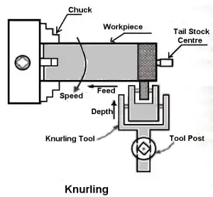

It is the method of manufacturing rough surface of embossing diamond formed pattern on a swish surface of a cylindrical job. Knurling provides a good fascinating surface on employment to forestall it from slithering once operated by hand.two sorts :
(a) straight or parallel, and
(b) diamond kind.
5.Thread Cutting
In thread cutting operation, there’s a definite magnitude relation of motion between the travel of tool and therefore the rotation of the spindle. This magnitude relation is directly establish by the lead screw that is connect to the shaper spindle through gears. General found out for thread cutting is show in Figure seven.15.
For cutting threads of various pitches, the stud (driver gear) and lead screw gear (driven gear) area unit modified as per desired magnitude relation of revolution between the spindle and therefore the lead screw. The magnitude relation between the teeth on stud and lead screw gear is

calculated by the given formula,
6. Grooving
Grooving, also known as necking, involves cutting narrow recesses or grooves on a cylindrical workpiece. The cutting edge of the grooving tool remains narrow and is specifically designed for this purpose.
7. Drilling
Drilling is the process of creating a round hole in the workpiece using a drill bit. The drill bit is held in the tailstock spindle, which supports and advances the tool into the rotating workpiece.
8. Boring
Boring enlarges an existing hole using a single-point cutting tool. The boring tool is mounted on a boring bar, which is held in the tailstock spindle or a tool post, depending on the setup.
9. Reaming
follows drilling or boring to improve the accuracy and surface finish of the hole. The reamer, held in the tailstock spindle, removes a small amount of material to ensure precise dimensions and smoothness.
Let me know if you’d like these steps turned into a visual flowchart or formatted for a training manual.
10.Chamfering operation: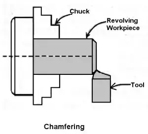
It is the operation of obtaining a bevelled surface at the sting of a cylindrical work. This operation is completed just in case of bolt ends and shaft ends. Chamfering helps to avoid harm to the sharp edges and defend the operation obtaining hurt throughout alternative operations. Chamfering on bolt helps to screw the nut simply.

11.Thread cutting:
It is the vital operation within the shaper to get the continual ”helical grooves” or ” threads’‘.
When the threads or coiling grooves area unit shaped on the out surface of the work is called external thread cutting. once the threads or coiling grooves area unit shap on the inner surface of the work is named internal thread cutting. The work is rotating between the 2 centres i.e., live centre and dead center os the shaper.

Here the tool is captive lengthwise to get the desired kind of the thread. once the tool is captive from right to the left we tend to get the left-hand thread. Similarly, once the tool is captive from left to the correct we tend to get the right-hand thread.
Here the motion of the carriage is provided by the lead screw. A combine of amendment gears drives the lead screw and by rotating the handle the depth of cut is controll.
12.Filling:
It is the finishing operation perform once turning. this can be done on a shaper to get rid of burrs, sharp corners, and feed marks on a work and conjointly to bring it to the dimensions by removing the terribly bit of metal.
The operation consists of passing a flat single-cut file over the work that revolves at a high speed. The speed is sometimes double that of turning.
13.Polishing:
This operation is perform after filing to enhance the surface quality of the workpiece.
Using progressively finer grades of abrasive material after filing results in a very smooth and bright surface finish. The lathe (or shaping machine) runs at high speeds, typically between 1500 and 1800 meters per minute, and oil is applied to the abrasive material to improve the finish and reduce heat.
- 14.Grooving:

It is the method of reducing the diameter of a work over a awfully slim surface. it’s done by a groove tool. A formation tool is comparable to the parting-off tool. it’s usually done at the tip of a thread or adjacent to a shoulder to depart atiny low margin.

15.Spinning:
it is the method of forming a skinny sheet of metal by revolving the task at high speed and pressing it against a support spindle. Support is additionally given from the support finish.
16.Spring Winding:
Spring winding is that the method of constructing a coiling spring by passing a wire around a shaft that is rotated on a chuck or between centers. atiny low hole is provided on the steel bar, that is supported by Tool Post and therefore the wire is allowed to meet up with it.
17.Forming:
It is the method of turning a lentiform, concave, or of any irregular form. Form-turning is also accomplished by the subsequent method:

Using a forming tool.
Combining cross and longitudinal feed.
Tracing or repetition a templet.
Forming tools don’t seem to be speculated to take away a lot of of the fabric and is employed principally for finishing shaped surfaces. Generally, 2 styles of forming tools area unit used straight and circular. The straight kind is employed for wider surface and therefore
MOCK TEST 1MOCK TEST 2